Fragment Shading Rate
The KHR fragment shading rate extension introduces the ability to selectively render at different sample rates within the same rendered image. This can be useful when rendering at very high resolutions or when the frequency content is not evenly spread through the rendered image. This tutorial demonstrates one way of controlling that sample rate by estimating the frequency content of each pixel of the rendered image.
The fragment shading rate extension can be enabled through
the VK_KHR_fragment_shading_rate
device extension and
the VkPhysicalDeviceFragmentShadingRateFeaturesKHR
device features. This sample demonstrates the attachment capability, in which the render pass directly references the
shading rate image through
a VkFragmentShadingRateAttachmentInfoKHR
struct attached to the .pNext of a sub-pass.
The image below shows the scene from this sample. Note the areas of high image variation in the center of each cube face, and the areas of low image variation in the sky and plain corners of each cube face.

Shading Rate Image
When used as an attachment, each pixel within the shading rate image controls a “texel”, or fixed region within the
output image, specified by shadingRateAttachmentTexelSize. For example, each pixel in the shading rate image might
control the shading rate of a 4x4 texel within the rendered image, since all output pixels of the texel are shaded at
the same rate, the shading rate image has a lower resolution. The number and type of possible shading rates is
controlled by the device and can be queried through
the vkGetPhysicalDeviceFragmentShadingRatesKHR
function, and may include shading rates that vary in both the x- and y-directions, for instance 1x2 or 4x2 pixel texels.
These supported shading rate values are provided to the “compute shader” when determining the optimal shading rate.
This sample demonstrates how to use a dynamic shading rate that responds to the frequency content of the image. To
achieve this, an attachment is added to the fragment shader at location=1, where the x- and y- derivatives are
estimated using the dFdx and dFdy functions. A separate compute shader then processes all the pixels within the
texel of the derivative image to determine the new fragment shading rate for the next image: texels with higher squared
derivatives calculated using dFdx and dFdy will be afforded a higher shading rate during the next frame compared to
texels with lower derivatives.
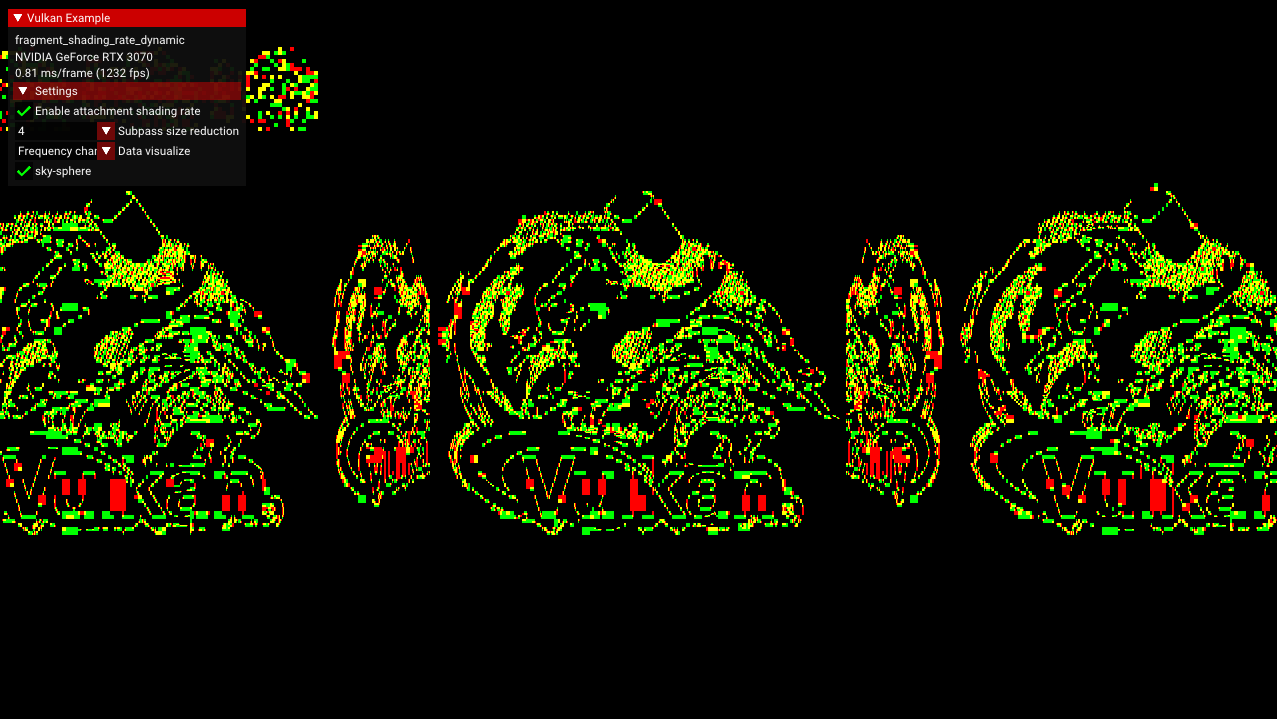
The frequency information is visualized below and can be accessed by selecting “Frequency” in the data visualization dropdown in the sample GUI.
Encoding the Shading Rate
Shading rates are encoded using 8-bit unsigned integers. For instance, the lowest shading rate of a 4x4 texel is given
by: (4>>1) | (4<<1), and the general case of a rate_x x rate_y texel is (rate_x>>1)|(rate_y<<1). Although
devices vary in their supported texel sizes, the maximum texel size is guaranteed to be no larger than 4x4.
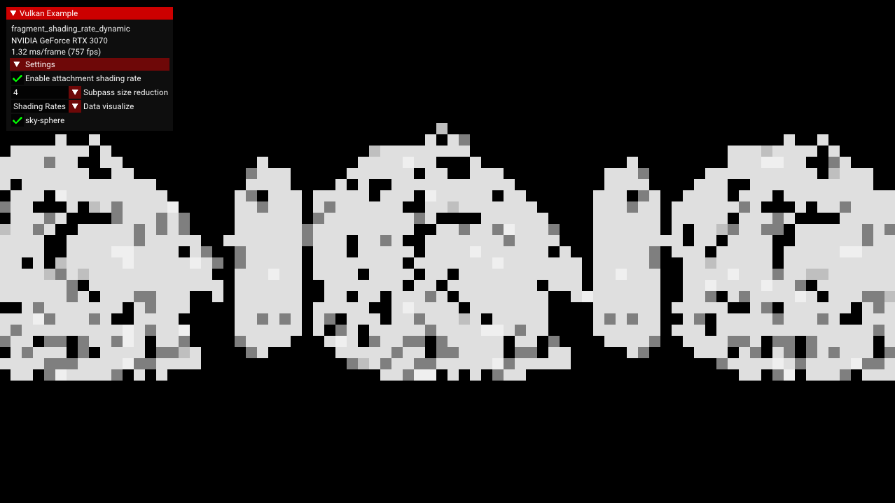
The image below shows the shading rate image, where lighter colors indicate areas that will have a high sample density. This visualization can be selected by choosing the “Shading Rates” dropdown selection in the sample GUI.
Implementation Details
This sample introduces a separate compute pipeline and several images to achieve dynamic shading rate:
shading_rate_image, the input image to the fragment shader to control shading rate,frequency_content_image, the output attachment from the fragment shader to record the derivatives at each pixel,shading_rate_image_compute, the output image from the “compute shader”
The frequency_content_image has type vec2 to store the squared x- and y-derivatives, which are used by the “compute
shader” to estimate the desired shading rate. Once the desired shading rate is estimated, the “compute shader” iterates
through the supported shading rates to find the one closest to the desired. This is converted to the 8-bit
representation of the format of the shading rate image:
uint rate_code = uint(optimal_rate_x >> 1) | (optimal_rate_y << 1);
This rate code is placed into shading_rate_image_compute.
Because of the device format requirements of the fragment shading rate extension (and the incompatibility of usage
flags), the shading_rate_image and shading_rate_image_compute images are separate and have different usage
flags: VK_IMAGE_USAGE_FRAGMENT_SHADING_RATE_ATTACHMENT_BIT_KHR for the shading rate attachment image
and VK_IMAGE_USAGE_STORAGE_BIT for the “compute” image (in addition to transfer bits). However, their content is
identical, and after the “compute shader” has completed, the contents from shading_rate_image_compute are copied
to shading_rate_image.
Calculating Frequency Information in a Separate Renderpass
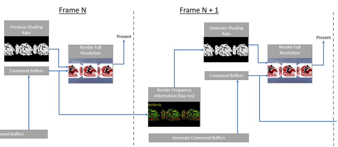
One problem with calculating the frequency information during the render pass is that each frame is using the previous frame’s shading rate, which results in a feedback loop that lead to unstable or “stutter” in the calculated frequency information. To prevent this problem, this sample introduces a separate renderpass that calculates the frequency information without using the shading rate attachment. To maintain performance, this renderpass is performed at a lower resolution controllable by the “Subpass size reduction” option in the sample GUI. In production systems, MSAA can also be disabled.
For instance, at a 4x4 reduction with MSAA disabled, the frequency information calculation is performed over only 1/128 as many samples as the full resolution with 8 MSAA samples. If the resulting shading rate image is used to reduce the full-resolution samples by half, then the total sample reduction is still greater than 40%.